diff options
| author | Robin Haberkorn <robin.haberkorn@googlemail.com> | 2021-02-11 08:11:08 +0100 |
|---|---|---|
| committer | Robin Haberkorn <robin.haberkorn@googlemail.com> | 2021-02-13 05:53:46 +0100 |
| commit | f16db7841a57ef04adf8d2f15f5a7bbbf3c89559 (patch) | |
| tree | 91c1c8e2e16b92b9ce515ba9abfd9d04a69855f9 /README.md | |
| parent | aa6c480f40241471d12c317c72acd94c2148a991 (diff) | |
| download | tmk7637-f16db7841a57ef04adf8d2f15f5a7bbbf3c89559.tar.gz | |
added documentation
Diffstat (limited to 'README.md')
| -rw-r--r-- | README.md | 280 |
1 files changed, 280 insertions, 0 deletions
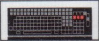
diff --git a/README.md b/README.md new file mode 100644 index 0000000..4425849 --- /dev/null +++ b/README.md @@ -0,0 +1,280 @@ +# VEB Robotron K7637 Replacement Controller and Firmware + + + +This repository hosts a replacement controller and firmware for the +[VEB Robotron K7637](https://www.robotrontechnik.de/index.htm?/html/zubehoer/tastaturen.htm#k7637) +keyboard based on the [TMK Keyboard Firmware](https://github.com/tmk/tmk_keyboard) +framework. +It allows you to attach the venerable keyboard to a modern PC using USB +while supporting most of its original features and many new features: + +* Full N Key Rollover. + The original firmware supported only 3-Key Rollover. +* The security key ("Bediensicherungsbaugruppe") is exposed as a key + between F19 and F24. +* Supports the [Unimap keymapping framework](https://github.com/tmk/tmk_keyboard/blob/master/tmk_core/doc/unimap.txt) + which eases adapting the keyboard layout and allows you to edit the keymap without + recompilation using the online [Keymap editor](http://www.tmk-kbd.com/tmk_keyboard/editor/unimap/). +* All of the seven LEDs are supported in one way or another: + * The Caps Lock LED does what you expect. + * Three of the five LEDs in the first row (G00-G04) display the standard + [Num Lock, Scroll Lock and Compose LED states](#LEDs). + * One of the LEDs displays the keyclick mode. + * The last LED in the first row (G53) displays the USB Kana LED state + but will also trigger the built-in buzzer. + * The five LEDs in the first row (G00-G04) are all dimmable via PWM. + This can be used for cool animations. +* The built-in buzzer is supported and its frequency can even be modulated. + It can be used as an error indication by enabling the USB Kana LED and + can even be [configured as your system beep](#Buzzer-As-System-Beep). +* There are currently two demo songs to show off the buzzer and LEDs. + Try pressing LSHIFT+ET1+ET2+F1 and LSHIFT+ET1+ET2+F2. +* Several keyclick modes are supported. + Press LSHIFT+ET1+ET2+Space to toggle them. + * Trigger a solenoid via a relay (or trigger only the relay). + The original hardware did not feature any solenoid. + * Emit a short beep on every keypress. + + + +## Building the Replacement Controller + +**This section is under construction.** + +You will need to acquire the following items: + +* [Teensy 2.0++](https://www.pjrc.com/store/teensypp.html). + The firmware has only been tested with this controller and we rely on its + particular shape. +* Pin Headers +* Lots of jumper cables +* If you want to attach the solenoid: + * Some Arduino-compatible relay breakout board + * A "flyback" diode + * _The solenoid is currently under evaluation._ +* (De)soldering equipment. + +First, you should desolder the UB 880 D processor and the 8212 IO chips. +If you don't plan on reusing these components, you can cut off all pins using +wire cutters. +Then heat up the pins on the backside of the PCB and when the solder melts +push them to the foreside. +Using pliers, you should be able to pull them off. +At least for the UB 880 D, all pin holes should be free of solder. + +Secondly, you should "neutralize" the following chips - it is sufficient +to cut their power pins: + +* The EEPROM. +* __FIXME__ + +Now, solder pin headers at least to the following pins on the backside of the +Teensy 2.0++: +__FIXME__ + +You should also solder pin headers to the following pins of the Teensy's top: +__FIXME__ + +Solder breadboard wires to the following pins of the Teensy: +GND (near the USB connector), VCC, E4, E5 + +Now, solder the wire from GND into pin 29 of the former UB 880 D, +the wire from VCC should be soldered to pin 11, the cable from E4 should go +into pin 10 (D6) and E5 should connect to pin 9 (D5): + + + +You can now push the Teensy into the former UB 880 D's place. +I recommend not to solder it immediately since you might want to test the firmware +first. +Most pins should already make contact without soldering. +It might be advisable to use an appropriate socket, so the Teensy can be +removed as often as you wish. +However, I have not tested this and you must take into consideration that it +increases the height of the construction. +Since the metal frame is going to rest above the Teensy, there might not be +enough space to house all of the jumper cables (unless of course, you +omit the pin headers on the Teensy's top and solder wires directly). + +Finally, you should connect the former UB 880 D's pin 20 (IORQ) to GND. +I did this during testing by soldering a pin header to one of the nearby +pads and using a jumper cable. +Later I made connection to the Teensy's GND pin using some additional solder +but you could also find some other GND on the board and solder a cable to it. + +Now, solder wires *on the backside* of the PCBs to the following pins of the former +8212 IO chip: 4, 6, 8, 10, 15, 17, 21 + + + +These wires connect to the Teensy in the following order: __FIXME__ + +Desolder the buzzer's 390R resistor and connect the side *facing away* from it +to a jumper cable. +It will connect to pin __FIXME__ of the Teensy. + +Connect the VCC, GND and the control pin of the relay using jumper cables with +the Teensy. +The control pin should be connected to PB3 of the Teensy. + +__FIXME__: How to connect the solenoid. + +You should now be ready to test your installation. +If everything goes well and you can determine that possibly dead keys are only +related to missing solder, you can fixate/solder your Teensy to the PCB. + +The endresult should look similar to this: + +  + +## Building and Flashing the Firmware + +First install some packages: + + sudo apt-get install build-essential gcc-avr avr-libc + +Furthermore, you will need to build and install the +[`teensy_loader_cli` flash tool](https://github.com/PaulStoffregen/teensy_loader_cli). + +Building the firmware should now be straight forward: + + git submodule update --init --recursive + make + +In order to flash the firmware, invoke `make teensy` and press +the Reset button on the Teensy 2.0++. +Once a firmware is running, you can also activate the Teensy Halfkay +bootloader by pressing LSHIFT+LCTRL+RALT+Pause (LSHIFT+ET1+ET2+PF11 on the K7637.50 layout). + +See also: https://github.com/tmk/tmk_keyboard/blob/master/tmk_core/doc/build.md + +## Keymap + +Since the firmware supports the Unimap keymapping framework, you can tweak the +layout without recompilation by uploading the firmware on +[Keymap Editor website](http://www.tmk-kbd.com/tmk_keyboard/editor/unimap/). + +The actual K7637 key arrangement differs significantly from the standard PC layout +assumed by Unimap. +It has been tried to choose PC equivalents of the K7637 keys by geometry. +If in doubt, have a look at [unimap_trans.h](unimap_trans.h) on how exactly the +keys are mapped. + +## LEDs + +The standard USB lock lights are located as follows: + +| capslock | LED next to the Caps Lock key (C99) | +| numlock | 1st LED on the top row (G00) | +| scrolllock | 5th LED on the top row (G04) | +| compose | 3rd LED on the top row (G02) | +| kana | 6th LED on the top row (G53) - *this also triggers the buzzer* | + +On Linux, you can manually set these LEDs using the following command: + + echo 1 | sudo tee /sys/class/leds/inputX\:\:Y/brightness + +Wheres *X* is a number and the *Y* is the name of the LED (eg. `input28::scrolllock`). +Writing a 0 disables the corresponding LED. + +## Buzzer As System Beep + +It is assumed that the "kana" LED is not really used as a regular keyboard LED. +On Linux, you can trigger the buzzer along with the fifth LED using the following command: + + echo 1 | sudo tee /sys/class/leds/inputX\:\:kana/brightness + +Whereas *X* is a number. +You can check which device it belongs to by consulting +`/sys/class/leds/inputX\:\:capslock/device/name`. + +There is also a script `k7637-beep.sh` for automatically finding the correct +LED node and triggering it for a short while. +This script might need root privileges (but see below). +You should install it into `/usr/local/bin`: + + sudo cp k7637-beep.sh /usr/local/bin/k7637-beep + +You should allow all users to set the keyboard's LEDs by installing some Udev rules: + + sudo cp k7637.rules /etc/udev/rules.d/50-k7637.rules + +**FIXME:** Maybe we should add a `make install` rule to install these files... + +You will have to reload the Udev rules using `sudo udevadm control --reload` in order to +try out this change immediately. +`k7636-beep` will now also run from non-root users (ie. without sudo). +If you deem the Udev rule above too liberal, you could of course also adapt it easily to grant +access only to a "led" group for instance and add your user to that group. + +`k7637-beep` is especially useful as a system bell. +You could use "xkbevd" (x11-xkb-utils package on Ubuntu) to automatically execute `k7637-beep` +whenever the X11 bell event is received. +To do so, create `~/.xkb/xkbevd.cf` with the following contents: + + Bell() shell "k7637-beep $d" + +Now you can automatically start xkbevd on login by creating the file `~/.config/autostart/xkbevd.desktop` +with the following contents: + + [Desktop Entry] + Comment=XKB event daemon + Exec=xkbevd -bg + Terminal=false + Type=Application + +Or you could use one of the dozen other ways to start xkbevd on login... +Note that it is important to have installed the Udev rule mentioned above since xkbevd will run +as the current user (although you might try setting its setuid flag if the Udev rule will not work +as expected). + +As an alternative to xkbevd, you might want to try [xbelld](https://gitlab.com/gi1242/xbelld). + +## TODO + +* It would be nice if we could control all LEDs and the buzzer including brightness/frequencies + from userspace (ie. from your PC). + Unfortunately, this does not seem to be supported by a standard USB HID keyboard. + There are at most 5 LEDs and they can only be on or off. + The only feature we're not yet using would be the keyboard backlight (see `BACKLIGHT_ENABLE`), + but it will work only for one LED or the buzzer. + For more, we'd have to create an USB composite device in order to provide a CDC device accepting + more complex commands. + Perhaps this will help: https://github.com/tmk/tmk_keyboard/issues/662 + * Perhaps we could also use a custom "HID report" descriptor? + See https://forums.obdev.at/viewtopic.php?t=9434 +* Now that we directly control the buzzer, it would also be possible to play custom waveforms. + This should be rather easy using an additional IRQ. + It could be used for additional keyclick modes. + First tests have not been promising as the result is too noisy. + But I tried to bit-bang a 2-bit wave at 44kHz. Perhaps it's better to PWM between + samples. +* Support more of the keyboard variants (different layouts). + Unfortunately, I own only the K7637-00 (or is it K7637-50?). + You should add a file `unimap_XX.c` for every variant and adapt `UNIMAP_K7637()`. + There can be more or less keys and a default mapping may make sense, etc. + Otherwise, the firmware should work unmodified on all models. +* PF0-7 are ADC pins. Perhaps we can use this to read out some of the keys analogue? + That would give us a keypress "strength". +* The Right Shift key is physically connected to the Left Shift key. + That's why there is only one keycode and there is no Right Shift entry in the keymap. + This could be remedied by a very simple hardware hack: + Cut either the row or the column trace and bridge it to some other unused position + in the keyboard matrix. + This would require merely an entry in unimap_trans and UNIMAP_K7637(). + Keyboards without this modification will also continue to work. + +## See Also + +The ["keyboard babel"](http://kbdbabel.org/) project contains a K7637 to PS/2 converter +(ie. should work with an unmodified board). +Unfortunately, the schematics and source code are nowhere to be found. +It shouldn't be hard to build a modern USB converter, though as the keyboard's +serial protocol is [well documented](docs/SerielleTastatur_K7637_XX_Betriebsdokumentation.pdf). +You merely need to add a current loop transceiver. +My particular board was simply broken, so I gave up on this approach. +The kbdbabel website was nevertheless invaluable for its [K7637 schematics](docs/kbdbabel_doc_robotron_k7637-50.pdf). +It also contains an [EEPROM dump](http://kbdbabel.org/rom/robotron-k7637_50-2716.bin) that could be of use +in restoring a K7637 board. +You might also be interested in the [IFFS connector pinout](http://kbdbabel.org/conn/kbd_connector_k7637.png). |