diff options
Diffstat (limited to 'README.md')
| -rw-r--r-- | README.md | 49 |
1 files changed, 36 insertions, 13 deletions
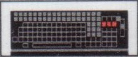
@@ -35,7 +35,7 @@ while supporting most of its original features and many new features: Try pressing LSHIFT+ET1+ET2+F1 and LSHIFT+ET1+ET2+F2. * Several keyclick modes are supported. Press LSHIFT+ET1+ET2+Space to toggle them. - * Trigger a solenoid via a relay (or trigger only the relay). + * Trigger a solenoid via a solenoid driver (or a relay breakout board). The original hardware did not feature any solenoid. * Emit a short beep on every keypress. @@ -45,8 +45,6 @@ You can watch a [demo video here](https://drive.google.com/file/d/16d42nZZ2FOZdN ## Building the Replacement Controller -**This section is under construction.** - You will need to acquire the following items: * [Teensy 2.0++](https://www.pjrc.com/store/teensypp.html). @@ -54,10 +52,6 @@ You will need to acquire the following items: particular shape. * Pin Headers * Lots of jumper cables -* If you want to attach the solenoid: - * Some Arduino-compatible relay breakout board - * A "flyback" diode - * _The solenoid is currently under evaluation._ * (De)soldering equipment. First, you should desolder the UB 880 D processor and the 8212 IO chips. @@ -131,12 +125,6 @@ It will connect to pin D0 of the Teensy. Desolder the IFFS cable. -Connect the VCC, GND and the control pin of the relay using jumper cables with -the Teensy. -The control pin should be connected to B3 of the Teensy. - -__FIXME__: How to connect the solenoid. - You should now be ready to test your installation. If everything goes well and you can determine that possibly dead keys are only related to missing solder, you can fixate/solder your Teensy to the PCB. @@ -145,6 +133,41 @@ The endresult should look similar to this:   +## Installing the Solenoid (Optional) + +If you want to install a solenoid, you will need the following components: + +* A 5V-rated solenoid like [this one](https://www.ebay.de/itm/113932404840). + Ideally it should be a push-trough solenoid (that can hit against something). +* A tranistor like IRFZ44N. TTL-level transistors should also work well. +* A diode. +* 10kOhm resistor (may be optional). + +The place near the LEDs in the top left corner turned out to be well suited for installing +small solenoids. +It can be placed between the PCB and metal frame and fixed with double-sides duct tape. +If you buy the same one as I did, you may also have to glue on some plastic or steel sheet +to the solenoid in order to increase its surface. + +The solenoid cannot be directly wired to the Teensy 2.0++, we will need to +build a simple solenoid driver. +In the most simple case, it can be assembled on a small breadboard that fits into +the keyboard's case. +It should be built according to the following circuit diagram: + + + +**NOTE:** Using one of the Arduino-compatible relay breakout boards +(together with a flyback diode of course) as a solenoid driver turned +out to be impractical. +It apparently draws too much power which will result in MCU crashes. +Perhaps this might work when using an externally powered USB hub. +You can however attach a bare relay breakout board (without solenoid) +to get some clicky feedback - but it's nowhere as load as even a small +dedicated solenoid. +Some of these breakout boards are LOW-active, so you might have to +tweak the code and invert the use of PB3 (solenoid trigger). + ## Building and Flashing the Firmware First install some packages: |